Difference between revisions of "Amplifiers"
(→Need of LNA) |
(→Comparison between LNA and PA) |
||
| (8 intermediate revisions by the same user not shown) | |||
| Line 21: | Line 21: | ||
=== Gain=== | === Gain=== | ||
An amplifier’s output/input magnitude ratio is gain. In RF, the gain is generally specified in logarithmic scale (dB). | An amplifier’s output/input magnitude ratio is gain. In RF, the gain is generally specified in logarithmic scale (dB). | ||
| − | [[File: | + | [[File:Amp1.gif|frame|center]] |
=== SNR (Signal to Noise Ratio) === | === SNR (Signal to Noise Ratio) === | ||
The ratio of signal power to the noise power, often expressed in decibels. | The ratio of signal power to the noise power, often expressed in decibels. | ||
| − | [[File: | + | [[File:Amp2.gif|frame|center]] |
=== NF (Noise Figure) === | === NF (Noise Figure) === | ||
It is measures of degradation of the SNR, caused by components in a RF signal chain. | It is measures of degradation of the SNR, caused by components in a RF signal chain. | ||
| − | [[File: | + | [[File:Amp3.gif|frame|center]] |
=== Bandwidth === | === Bandwidth === | ||
| Line 42: | Line 42: | ||
Noise figure of a component has been defined above. But one can also define the noise figure of a system consisting of multiple components connected in series. NF of this kind of system is define in a very similar way as above with SNRin is the SNR of input to the system and SNRout is the SNR of the output of the system. <br \> | Noise figure of a component has been defined above. But one can also define the noise figure of a system consisting of multiple components connected in series. NF of this kind of system is define in a very similar way as above with SNRin is the SNR of input to the system and SNRout is the SNR of the output of the system. <br \> | ||
If we know the individual noise figures, we can calculate the noise figure of the system using this formula, | If we know the individual noise figures, we can calculate the noise figure of the system using this formula, | ||
| − | [[File: | + | [[File:Amp4.gif|frame|center]] |
| − | where Fn is the noise factor for the n-th device, and Gn is the power gain (linear, not in dB) of the n-th device. | + | where Fn is the noise factor for the n-th device, and Gn is the power gain (linear, not in dB) of the n-th device. |
=== Need of LNA === | === Need of LNA === | ||
| − | [[File:Amplifiers5.png| | + | [[File:Amplifiers5.png|thumb|500px|RF front end. Image reproduced from [https://commons.wikimedia.org/wiki/File:Superheterodyne_receiver_block_diagram_2.svg here]]] |
The signal received by the antenna has a lot of noise. The signal is very close to noise level and any degradation of SNR of the signal will make the signal level go below the noise floor. This will cause the signal to be lost and we can’t get the data from the signal. As we from the above formula the NF of the system is mainly determined by NF of the first device if the gain is very high. As LNA is has a very low noise figure and a very high gain, so the noise figure of the system is very low. The arrangement of antenna followed by LNA is called as an active antenna. Thus LNA is one of the most important part of the RF front end. | The signal received by the antenna has a lot of noise. The signal is very close to noise level and any degradation of SNR of the signal will make the signal level go below the noise floor. This will cause the signal to be lost and we can’t get the data from the signal. As we from the above formula the NF of the system is mainly determined by NF of the first device if the gain is very high. As LNA is has a very low noise figure and a very high gain, so the noise figure of the system is very low. The arrangement of antenna followed by LNA is called as an active antenna. Thus LNA is one of the most important part of the RF front end. | ||
| Line 53: | Line 53: | ||
* '''Noise Figure:''' The noise figure should be as low as possible. | * '''Noise Figure:''' The noise figure should be as low as possible. | ||
* '''Linearity:''' If your signal is a broadband signal, the linearity of the the LNA matters. OIP3 (Third Order Intercept Point) is a measurement of the linearity of an LNA. Linearity means that the Harmonics are not produced. (Further explanation of OIP3 can be found [https://en.wikipedia.org/wiki/Third-order_intercept_point here]) | * '''Linearity:''' If your signal is a broadband signal, the linearity of the the LNA matters. OIP3 (Third Order Intercept Point) is a measurement of the linearity of an LNA. Linearity means that the Harmonics are not produced. (Further explanation of OIP3 can be found [https://en.wikipedia.org/wiki/Third-order_intercept_point here]) | ||
| − | [[File:Linearity.png|frame|center]] | + | [[File:Linearity.png|frame|center|Basic Characteristics of an LNA. Image reproduced from the datasheet of ADL5523, which can be found [http://www.analog.com/media/en/technical-documentation/data-sheets/ADL5523.pdf here]]] |
* '''Matching Circuits:''' The input and the output must be matched to 50ᘯ for optimal performance. Every device has a Input and output impedance. These are the impedances looking from input and output respectively. For maximum transfer of power all the impedances of connecting components or tracks or wires should be same. If there is a mismatch the signals may get reflected and damage the amplifier. For more reading one can read Transmission lines. <br \> | * '''Matching Circuits:''' The input and the output must be matched to 50ᘯ for optimal performance. Every device has a Input and output impedance. These are the impedances looking from input and output respectively. For maximum transfer of power all the impedances of connecting components or tracks or wires should be same. If there is a mismatch the signals may get reflected and damage the amplifier. For more reading one can read Transmission lines. <br \> | ||
If there is a mismatch between input of a connected device and output of the other device and matching circuit has to be designed for impedance matching. Example is shown in the following figure. | If there is a mismatch between input of a connected device and output of the other device and matching circuit has to be designed for impedance matching. Example is shown in the following figure. | ||
| − | [[File: | + | [[File:Amplifiers6.png|frame|center|Impedance Matching Circuit]] |
== Power Amplifier (PA) == | == Power Amplifier (PA) == | ||
| Line 95: | Line 95: | ||
|} | |} | ||
| + | ''The values in the table are take from datasheets for LNA from Analog Devices (ADL5523) and Power Amplifier RF5110G.'' | ||
| + | ---- | ||
If you are done reading this page, you can go back to [[Communications Subsystem]] | If you are done reading this page, you can go back to [[Communications Subsystem]] | ||
Latest revision as of 22:01, 19 February 2018
Contents
What is an Amplifier?
An amplifier (aka amp) is an electronic device that can increase the power of a signal. An amplifier uses electric power from a power supply to increase the amplitude of a signal. The amount of amplification provided by an amplifier is measured by its gain: the ratio of output voltage, current, or power to input. An amplifier is a circuit that has a power gain greater than one.
An amplifier is an electrical two-port network that produces a signal at the output port that is a replica of the signal applied to the input port, but increased in magnitude. There are various types of amplifiers, some can change the phase of the input signal, some can cause distortion. According to what an amplifier does to input signal, they are divided into various classes. Amplifier Classes represent the amount of the output signal which varies within the amplifier circuit over one cycle of operation when excited by a sinusoidal input signal.
- Class A - 360° conduction
- Class B - 180° conduction
- Class AB - Slightly more than 180° conduction
- Class C - Slightly less than 180° conduction
One can find a very good information on different classes of amplfier by visiting http://www.electronics-tutorials.ws/amplifier/amplifier-classes.html
Need of amplifiers in Communications
Amplifiers play a major role in communications. The strength of a communication link is determined by the strength of the signal received at the receiver. One simple way to make a good communication link is that we transmit the signal with greater power at the transmitter side. The signal produced at the transmitter end is of very low power, so we need to increase the power of the signal and then transmit. This “increasing the power” is also known as amplification. The amplification is done by an amplifier called as Power Amplifier.
It is not always possible to increase the transmission power indefinitely such that every receiver can get the required power of the signal. Especially in satellite communication there is a constraint in the transmission power as the solar panels produce a fixed amount of power (For further details read Power Budget). One method that can be used is to amplify the signal at the receiver end. After the signal is capture by the antenna, we can amplify the signal using a amplifier. After amplification the signal is filter, this process if called conditioning of the signal. After conditioning the signal can be demodulated and interpreted. This amplifier is called as Low Noise Amplifier (LNA).
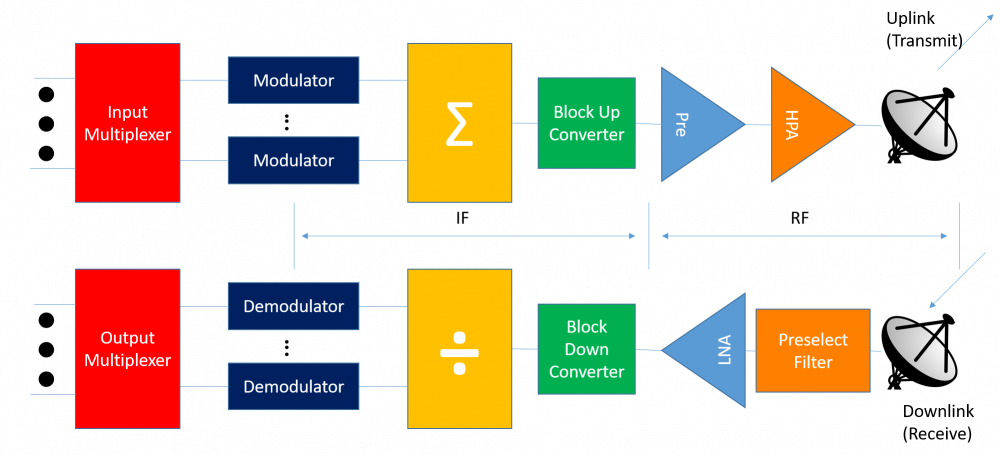
Amplification of signal is the first step in receiving process while is the last in transmission process. You can see this in the following diagram. Generally amplifiers are represented using a triangle. In the figure HPA - High Power Amplifier and LNA - Low noise amplifier. You can see that in both, the amplifier are connected to the antenna.

Gain
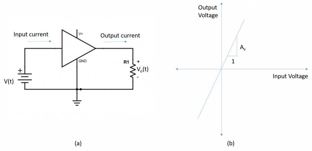
An amplifier’s output/input magnitude ratio is gain. In RF, the gain is generally specified in logarithmic scale (dB).
SNR (Signal to Noise Ratio)
The ratio of signal power to the noise power, often expressed in decibels.
NF (Noise Figure)
It is measures of degradation of the SNR, caused by components in a RF signal chain.
Bandwidth
The bandwidth of an amplifier is the range of frequencies for which the amplifier gives desired performance.
For more terms related to amplifiers, visit: https://en.wikipedia.org/wiki/Amplifier_figures_of_merit
Low Noise Amplifier (LNA)
A low-noise amplifier (LNA) is an electronic amplifier that amplifies a very low-power signal without significantly degrading its signal-to-noise ratio. An amplifier increases the power of both the signal and the noise present at its input. It does not add additional noise.The function of the LNA is to take the extremely weak(-100 dBm) and uncertain signal from the antenna, and amplify it to a more useful level. LNA is a broadband device and have a high gain. LNA has a low noise figure.
Formula for Noise Figure of a System
Noise figure of a component has been defined above. But one can also define the noise figure of a system consisting of multiple components connected in series. NF of this kind of system is define in a very similar way as above with SNRin is the SNR of input to the system and SNRout is the SNR of the output of the system.
If we know the individual noise figures, we can calculate the noise figure of the system using this formula,
where Fn is the noise factor for the n-th device, and Gn is the power gain (linear, not in dB) of the n-th device.
Need of LNA

The signal received by the antenna has a lot of noise. The signal is very close to noise level and any degradation of SNR of the signal will make the signal level go below the noise floor. This will cause the signal to be lost and we can’t get the data from the signal. As we from the above formula the NF of the system is mainly determined by NF of the first device if the gain is very high. As LNA is has a very low noise figure and a very high gain, so the noise figure of the system is very low. The arrangement of antenna followed by LNA is called as an active antenna. Thus LNA is one of the most important part of the RF front end.
Parameters to be considered while selecting LNA
- Gain: The gain should be high. The reason being low NF of system.
- Noise Figure: The noise figure should be as low as possible.
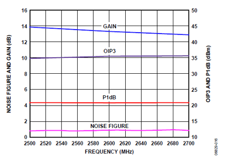
- Linearity: If your signal is a broadband signal, the linearity of the the LNA matters. OIP3 (Third Order Intercept Point) is a measurement of the linearity of an LNA. Linearity means that the Harmonics are not produced. (Further explanation of OIP3 can be found here)

- Matching Circuits: The input and the output must be matched to 50ᘯ for optimal performance. Every device has a Input and output impedance. These are the impedances looking from input and output respectively. For maximum transfer of power all the impedances of connecting components or tracks or wires should be same. If there is a mismatch the signals may get reflected and damage the amplifier. For more reading one can read Transmission lines.
If there is a mismatch between input of a connected device and output of the other device and matching circuit has to be designed for impedance matching. Example is shown in the following figure.
Power Amplifier (PA)
A radio frequency power amplifier (RF power amplifier) is a type of electronic amplifier that converts a low-power radio-frequency signal into a higher power signal.RF power amplifiers drive the antenna of a transmitter. A voltage or a current amplifier does not have sufficient POWER (volts V x current I).Thus we need a Power amplifier.
Parameters to be considered while selecting a PA
- Gain: The gain should be large, typically 30-40 dB
- Input Power: Power Amplifier consumes a lot of power as it has to amplify power and drive a low impedance output (Antenna). A PA consuming lower power is preferred when power is limited.
- Maximum Input Signal Power for avoiding Saturation: The datasheet provides the maximum power the input signal can have. If the input power is very large the device goes in saturation thus does not give the desired gain.
- Operating Frequency: One must be very careful while selecting the PA IC. He/she should check if the IC’s working frequency range matched the input signal frequency.
Comparison between LNA and PA
| LNA | PA | |
| Placement | Part of the receiver (just after the antenna) | Part of the transmitter (just before the antenna) |
| Input Signal Power | -130 dBm to -90 dBm | 0 dBm to 10 dBm |
| Typical Gain | 10 to 15 dBm | 30 to 40 dBm |
| Power Consumed | Very Low | Very High |
| Heat Sinks | Not required | Generates a lot of heat. Heat sinks necessary. |
The values in the table are take from datasheets for LNA from Analog Devices (ADL5523) and Power Amplifier RF5110G.
If you are done reading this page, you can go back to Communications Subsystem


