Antenna
The sole component which changed the world of communication technology from wired to wireless is antenna. That is because antennas convert the electromagnetic fields to current in antenna (Reception) and current flowing through them into the electromagnetic fields (Transmission). These electromagnetic waves associated with antenna can traverse freely through air giving it “wireless” capabilities.
While selecting an antenna one would like to know about the characteristics of an antenna. We will now see what these characteristics are and how they affect the working and usage of antennas.
Contents
Characteristics of an Antenna
Field Regions
There are three types of field regions:
- Reactive near field: It is in immediate vicinity of antenna. The E-fields and H-fields here are 90° out of phase.
- Radiative near field: Here the radiation pattern (radiated power vs direction) varies considerably with distance (away from antenna).
- Far field: Here the radiation pattern is constant with respect to distance from antenna. Any antenna placed in far field of another antenna is not affected by its radiations.
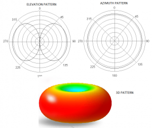
Radiation Pattern
The graphical representation of power distributed as a function of direction in the far field of an antenna is it’s radiation pattern. Let's say we place an antenna at the centre of an imaginary sphere. Now we take a device which can measure the energy of radiation at a place and take readings using it at all the points on the sphere. The decibel plot of power received as a function of elevation or azimuth is radiation plot. More commonly, a polar plot is plotted with radius describing normalised radiation power to draw the radiation pattern. The function of power with azimuth and elevation is known as radiation function.
These plots are very helpful as they give insight to many properties of antennas such as gain, directivity and also assist in visualization of power distribution in the real scenario.
Example: The radiation pattern for dipole antenna is as follows.
Frequency
An antenna is always designed for a specific frequency. Once the frequency is set, the wavelength of antenna is set too and all the dimensions of antenna are specified in terms of its wavelength.
Directivity
As the name suggests, directivity is the measure of how directed the antenna radiation pattern is. That is how much an antenna transmits in a particular direction as opposed to transmitting uniformly in all directions. The radiation pattern can be depicted as a function of azimuth angle and elevation angle. The ratio of max power in radiation pattern function to the average power of radiation gives us the directivity of any antenna. Mathematically, if F(Θ,Φ) denotes the radiation function, directivity can be described by:

