Antenna
The sole component which changed the world of communication technology from wired to wireless is antenna. That is because antennas convert the electromagnetic fields to current in antenna (Reception) and current flowing through them into the electromagnetic fields (Transmission). These electromagnetic waves associated with antenna can traverse freely through air giving it “wireless” capabilities.
While selecting an antenna one would like to know about the characteristics of an antenna. We will now see what these characteristics are and how they affect the working and usage of antennas.
Characteristics of an Antenna
Field Regions [1]

There are three types of field regions:
- Reactive near field: It is in immediate vicinity of antenna. The E-fields and H-fields here are out of phase and there distribution is very complex and it requires large computations to find that distribution. The distance from antenna is deciding factor in this region. It's boundary is given by
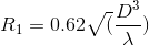 .
. - Radiative near field: Here too, the radiation pattern (radiated power vs direction) varies considerably with distance (away from antenna). The E-fields and H-fields are in phase here. It's boundary is given by
 .
. - Far field: Here the radiation pattern is constant with respect to distance from antenna. Any antenna placed in far field of another antenna is not affected by its radiations. It extends to infinity.
Radiation Pattern
The graphical representation of power distributed as a function of direction in the far field of an antenna is its radiation pattern. Let's say we place an antenna at the centre of an imaginary sphere. Now we take a device which can measure the energy of radiation at a place and take readings using it at all the points on the sphere. The decibel plot of power received as a function of elevation or azimuth is radiation plot. More commonly, a polar plot is plotted with radius describing normalised radiation power to draw the radiation pattern. The function of power with azimuth and elevation is known as radiation function.
These plots are very helpful as they give insight to many properties of antennas such as gain, directivity and also assist in visualization of power distribution in the real scenario.
Example: The radiation pattern for dipole antenna is as follows.


Frequency
An antenna is always designed for a specific frequency. Once the frequency is set, the wavelength of antenna is set too and all the dimensions of antenna are specified in terms of its wavelength.
Directivity


As the name suggests, directivity is the measure of how directed the antenna radiation pattern is. That is how much an antenna transmits in a particular direction as opposed to transmitting uniformly in all directions. The radiation pattern can be depicted as a function of azimuth angle and elevation angle. The ratio of max power in radiation pattern function to the average power of radiation gives us the directivity of any antenna. Mathematically, if F(Θ,Φ) denotes the radiation function, directivity can be described by: [2]

Based upon directivity, antennas can be divided in three groups:
- Isotropic: An isotropic antenna is an ideal antenna which radiates uniform power in all directions. Hence its directivity would be 1(0 dB). It's radiation pattern is a sphere.
- Omnidirectional: Omnidirectional antenna radiates uniform power in planes described by a normal i.e. in any plane perpendicular to a normal, the radiation power would be equal in all directions. Hence the radiation pattern for a simple omnidirectional antenna resembles a “doughnut” as shown in the figure. But it's pattern can also be complex like this figure.
- Directional: Directional antennas can radiate greater amount of power in one specific direction compared to any other direction. Their directivities are very high. They have complicated (and often interesting) radiation patterns.
| Antenna Type | Typical Directivity | Typical Directivity (dB) |
| Short Dipole | 1.5 | 1.76 |
| Half-wave dipole | 1.64 | 2.15 |
| Patch (Microstrip) | 3.2-6.3 | 5-8 |
| Horn | 10-100 | 10-20 |
| Dish | 10-10000 | 10-40 |
As is evident, directivity can vary greatly with type of antenna. Hence it's important to understand and know directivity before selecting antenna for your application. Like, if you are going to receive/transmit signal from/to any direction, it is better to use antenna with low directivity. Similarly in an application where the direction of signal is fixed, highly directed antennas work way better.
Half Power Beamwidth

As we have directional antennas, one obvious question we can get for what angle we can get good radiation power? Although the answer to this question also depends on receiving setup, it is generally defined as the point where the power output drops to half its maximum value. When converted to dB it amounts to approx 3 dB loss, hence it is also called 3 dB point. In one plane, there are going to be two such points. The angular separation between the two points is half power beamwidth or 3 dB beamwidth.
Antenna Efficiency [4]
Antenna efficiency is basically ratio of power radiated from the antenna to the power delivered to antenna. In short, it denotes the losses due to antenna. Antenna efficiency could be further categorized into radiation efficiency and impedance mismatch, total efficiency being the product of the two. The losses could be attributed to three major factors:
- Conduction losses: These are losses due to finite conductivity of elements of antenna
- Dielectric losses: The electric fields induce current in the nearby dielectrics reducing the energy carried by fields. These are dielectric losses
- Impedance mismatch: Some part of power delivered to antenna by transmitter is reflected back due to mismatch in impedance of antenna driving circuit(transmitter) and antenna and hence results in loss of power. We will talk about impedance mismatch and matching later.
Voltage Standing Wave Ratio (VSWR)
Impedance matching, which is described in above section, is quantified using the VSWR. It basically describes the power reflected back from the antenna-transmitter junction. More reflected power signifies greater impedance mismatch loss. VSWR is related to reflection coefficient (more commonly known as s11, and represents how much power is reflected back from antenna) by the following formula
Lower the VSWR, better is the antenna impedance matched. VSWR can be easily found out using Vector Network Analyser (VNA).
Antenna Gain
Antenna gain describes the power in the direction of peak power of any antenna with respect to an lossless isotropic antenna (100% efficiency and 1 directivity) when both are excited with same power. Simply speaking antenna gain takes into account both directivity and antenna efficiency and mathematically it is product of those two.
Antenna Gain = Antenna Efficiency x Directivity [5]
Similar to directivity, antenna gain can vary considerably with type of antenna and hence the type of antenna to be selected is highly application specific
Polarization
Polarization is very easily visualised as pattern traced out by the E-field in any electromagnetic wave.
 Electromagnetic wave. Image reproduced from here |


For example in the the above figure, when only E-field component of the electromagnetic wave is traced out on screen perpendicular to the direction of propagation of the electromagnetic wave, we get a straight line. Hence the polarization of this kind of electromagnetic wave is called linear.
Based on polarization there are three major types of waves:
- Linearly polarized: The above wave is a example of linearly polarised wave. In linear polarization, the line traced by E-field can be in any orientation.
- Circularly polarized: Consider two linearly polarised waves of equal magnitude perpendicular to each other. If we create a phase difference of 90° between them and add them, we will get a circular polarized wave. i.e. the E-field of the wave will trace out a circle. The circle can right handed (Right Hand Circular Polarization or RHCP) or left handed (Left Hand Circular Polarization or LHCP) depending on which wave is leading or lagging.
- Elliptically polarized: If the two linearly polarized waves used for circular polarization have unequal magnitude or are added with phase difference not 90° or 0° or integral multiple of 90°, then the resulting polarization will be elliptical. The ellipse, again, can be right handed or left handed.
 Linear, Circular and Elliptical Polarization. Image reproduced from here |
Now, the polarization of any antenna is simple the polarization of electromagnetic waves radiated by that antenna. The reason why polarisation of antenna is so important is it is useful in determining the losses while making the link budget.
Balun
Balun is not necessarily a characteristic of an antenna. It is more of an additional component in some antenna. We suggest that you read about various types of antennas before reading about balun as it is used only for designing an antenna. Balun is derived from the expression ‘balanced to unbalanced’.[6] It simply converts an unbalanced signal to a balanced signal. To put it very simply, a coaxial cable which has outer coating as ground (zero potential) and inner core as signal (some voltage V) is an unbalanced signal. While a twisted cable pair in which one wire has potential V and other has potential -V is a balanced signal. Some antennas such as monopole work when unbalanced signal are fed to it. On the other hand dipole antenna require unbalanced signal (+V, -V). Transmitting circuits usually generate unbalanced signal. Hence to convert unbalanced signal to balanced signal baluns are required.[7]
There are numerous types of baluns. Some use transformers and autotransformers, some acts as RF choke. Ham enthusiasts often use ‘delay line type’ baluns. They are nothing but introducing delay using transmission lines and using it to balance a signal.
Decibel (dB)
Again, it's not a characteristic of antenna but there is always a lot of confusion regarding this. Power in decibel is defined as, [8]
Here the reference power is 1W when power is denoted in Watts. Hence the resultant decibel is known as dBW. When power is denoted in milliwatts, the resultant decibel is denoted by dBm. Here the reference power is 1 mW.
When decibels are used to describe gain, apart from dBW and dBm sometimes dBi and dBd are also used. dBi denotes gain of the antenna with respect to that of isotropic antenna. As the gain of an isotropic antenna is 1, nothing changes numerically. dBd denotes gain of antenna with respect to that of a standard half wave dipole antenna (gain is 2.15). Numerically, dBd = dB - 2.15.
Decibel is widely used as it easier to perceive quantities when they are represented in decibels.
Antenna Types and their Characteristics
Half wave dipole

- Dipole antennas are one of the earliest used antennas. The antenna used by Hertz in his experiment to transmit electromagnetic waves was also similar to dipole antenna. Its geometry is linear and its structure is, to simply speak, two wires in a line.
- As the name suggests, the length of this antenna is half of its wavelength at the desired frequency of operation. The signal is feeded to this antenna midway. It has an omnidirectional radiation pattern and linear polarization.
- It has low directivity (2.15 dB) and input impedance of 73 + j42.5 ohm. [9] The antenna can be made resonant (input impedance purely real) by reducing length of antenna to 0.48 fraction of wavelength
Folded dipole

- Folded dipole antenna is resonant and radiates well when its length is odd integer multiple of half wavelength (eg. 0.5λ, 1.5λ, 2.5λ...etc).
- Input impedance of half wavelength folded dipole is four times that of normal half wavelength dipole i.e approx. 280 ohms.
- It is linearly polarised.
- Radiation pattern similar to half wavelength dipole.
Monopole

- It is the simplest kind of antenna. It's just a wire and a ground plane with the wire perpendicular to ground plane. From electromagnetic theory, the ground plane acts as a mirror and the monopole antenna acts as a dipole antenna of twice its length. Hence most of its properties are same as a dipole antenna of twice length
- The main points of difference between a monopole and dipole are its resonant length, input impedance and directivity. A dipole resonates at 0.48 fraction of wavelength while the monopole resonates at half this length as monopole acts as a dipole twice its length. The input impedance of monopole is half of a dipole of twice length i.e. 36.5 + j21.25 ohm (for length 0.25*wavelength). The directivity of monopole is twice (+3 in dB) of dipole antenna i.e. 5.15 dB. [10]
- In this discussion we have assumed the ground plane to be infinite. It is not so in any practical application, so the characteristics of this antenna can change slightly due to finite ground plane. The characteristics can be simulated using various simulation softwares.
- They are a very popular choice due to their small size simplicity and are used in almost all common antenna applications.
Yagi

- While monopole and dipole are omnidirectional antennas, yagi is a directional antenna. It's made up of only wires and has only one feed (where you apply signal). It has three elements - feed (folded dipole in the diagram), directors and reflector. All the three elements are attached to a single long rod which is called “boom”. The feed, directors and reflector are perpendicular to the boom and in the same plane. Their order is - reflector then feed then directors. Feed is the element where signal to be transmitted is applied. The feed is typically a dipole or a folded dipole. The feed is made resonant in the presence of other elements. This length is different from the resonant length of isolated antenna. It is mostly calculated using simulations.
- The other two elements are also called parasitic elements as they are not excited by any signal. The directors are used to increase the directivity of the antenna. Increasing the number of directors increases directivity of the antenna. Their length is slightly less than the feed element and progressively decreases when we move further away from feed. The number of directors can be as large as 20-30. The reflector, as the name suggests, seem to reflect radiation thus decreasing its radiation in unwanted direction. Usually only one reflector is used but antennas having more than one reflectors have been designed. They are physically longer than feed element. Its theory of operation is quite interesting, so do give it a read.
- About its characteristics, it is a highly directive antenna whose gain can go upto 20dBi.[11] Its bandwidth is typically small. The input impedance is that of the feed which can be simulated.
- To design this antenna, quite a lot of variables are needed to be decided. These include length of all elements and their spacing. All these variable belong to a small range of lengths and are tweaked using simulations before actually making the antenna.
- Most of you may have seen these kind on antennas on your roof. They were widely used as television antennas and even today are very popular amongst ham enthusiasts. They are quite easy to make and its directivity can be increased by just increasing the number of directors. They are regarded as IEEE Milestone. Their importance just can’t be overstated.
Crossed Yagi

- All the antennas we have looked at so far were linearly polarised antennas. But in actuality circular polarised can be made quite easily from all the linearly polarised antennas. As we mentioned in polarisation, circular polarization is constructed simply from two equal magnitude linearly polarized orthogonal signals which are 90° out of phase. Antennas with same geometry will have same output radiation for same input. Hence two linearly polarized antennas with same geometry placed in such a way such that their output is orthogonal to one another and a 90° phase shifted signal given to one of them will result in circular polarisation antenna. The antennas have to placed in near field region of each other.
- In a crossed Yagi antenna, two yagi antennas are used to achieve circular polarization. Both the antennas are placed geometrically orthogonal to one another and 90° phase shifted signals are given to their feed. Hence it acts as a circularly polarised antenna. Usually this 90° phase shift is added by introducing an additional cable of length about 0.25*wavelength (actually the length also depend upon the kind of wire used. The phase difference due to transmission cable is its path difference times velocity factor which depends on cable). Weather it's RHCP or LHCP can actually be changed by changing its connections. [12]


If you are done reading this page, you can go back to Communications Subsystem
References
- ↑ http://www.giangrandi.ch/electronics/anttool/regions.shtml
- ↑ https://en.wikipedia.org/wiki/Directivity
- ↑ http://www.antenna-theory.com/basics/directivity.php
- ↑ http://www.antenna-theory.com/basics/efficiency.php
- ↑ https://en.wikipedia.org/wiki/Antenna_gain
- ↑ https://en.wikipedia.org/wiki/Balun
- ↑ http://searchnetworking.techtarget.com/definition/balun
- ↑ http://www.antenna-theory.com/definitions/decibels.php
- ↑ http://www.antenna-theory.com/antennas/halfwave.php
- ↑ http://www.antenna-theory.com/antennas/monopole.php
- ↑ https://en.wikipedia.org/wiki/Yagi%E2%80%93Uda_antenna
- ↑ http://www.qsl.net/dk7zb/Cross-Yagi/crossyagi.htm