AIRCRAFT ACCIDENT
INVESTIGATION
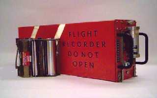
The “Black Box”
With any airplane crash, investigators turn to
the airplane's flight data recorder
(FDR) and cockpit voice recorder
(CVR), also known as "black boxes," for answers.
Following any airplane accident in the United
States, safety investigators from the
National Transportation Safety Board (NTSB) immediately begin searching for the
aircraft's black boxes. These
recording devices, which cost between $10,000 and $15,000 each, reveal details
of the events immediately preceding the accident.
The history of Flight Data Recorders (FDRs)
Actually, the Wright Brothers first used a device to
record propeller rotations, which can be called the most primitive form of
flight data recording. However, the widespread use of aviation recorders didn't
begin until the post-World War II era. Since then, the recording medium of
black boxes has evolved in order to record much more information about an
aircraft's operation.
Flight recorders were first introduced in the
1950's and used spools of stainless steel wire or tape as the recording medium.
This was housed in a 'survival box' usually located in the aft (rear) end of an
airplane. These first generation flight recorders used metal foil as the
recording medium. One single strip was capable of recording 200 to 400 hours of
data. Scribe arms attached to moving coil meters and air pressure mechanisms
literally scratched traces on to the moving foil medium.
A first generation flight recorder.
The first mandate to fit flight recorders on
certain aircraft was published by the
Civil Aeronautics Administration (later the FAA) on August 1st, 1958. A similar rule was issued by
the UK Government in 1960. It said that all civilian
passenger carrying aircraft over 20,000lbs should carry a crash protected
flight
recorder. The first improvements came about in 1965, when flight recorders
were required to be painted bright yellow or orange, so making them easier to
find after a crash. As the requirements to record more data over the years was
increased the second generation of FDRs came about and, around the 1970's, the
Flight Data Acquisition Units (FDAUs) were introduced.
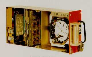
A second generation flight recorder.
FDAUs process sensor data digitizes and formats
it so it can be transmitted to the FDR. These second generation digital FDRs,
called DFDRs used tape (like audio tape) 300 to 500 ft long capable of
recording 25 hours of data. Again this was all housed in a crash protection
box.
In the late 1980's all first generation FDRs were
required to be replaced with
second generation DFDRs.
In 1991 another rule change required the installation
of digital FDAUs, or
DFDAUs, with DFDRs, using solid state memory. This system was required to
record 34 parameters. They were capable of processing 100 different sensor
signals per second for a 25 hour period.
Recording and Storage
of Data
Most of the black boxes in use
today use magnetic tape, first
introduced in the 1960s, or solid-state
memory boards, which came along in the 1990s and are replacing all the
tape based recorders since then.
Solid-state
recorders are considered much more reliable than their magnetic-tape and use
stacked arrays of memory chips, so they don't have moving parts. Hence they
require less maintenance and have more chances of survival during a crash. Data
from both the CVR and FDR is stored on stacked memory boards inside the crash-survivable
memory unit (CSMU) which is a cylindrical compartment on the recorder.
The stacked memory boards are about 1.75 inches (4.45 cm) in diameter and 1
inch (2.54 cm) tall and have enough digital storage space to accommodate two
hours of audio data for CVRs and 25 hours of flight data for FDRs.
|
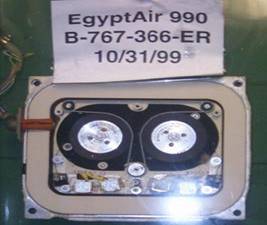
The magnetic tape inside the flight
data recorder from EgyptAir Flight 990, which crashed on October
31, 1999
|
Airplanes are equipped with sensors that gather
data like acceleration, airspeed, altitude, flap settings, outside temperature,
cabin temperature and pressure, engine performance etc. Magnetic-tape recorders
can track about 100 parameters, while solid-state recorders can track more than
700 in larger aircraft.
All of the data collected by the airplane's
sensors is sent to the flight-data
acquisition unit (FDAU) at the front of the aircraft, often in the electronic equipment bay under the
cockpit. The flight-data acquisition unit takes the information from the
sensors and sends it on to the black boxes. Both black boxes are installed in
the tail of the plane -- putting them in the back of the aircraft increases
their chances of survival, and are powered by one of two power generators that
draw their power from the plane's engines.
|
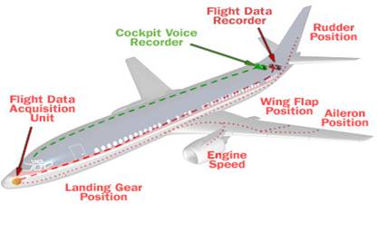
Basic components and operation of an
aviation recording system
|
Flight Data Recorders
The flight data recorder (FDR)
is designed to record the operating data from the plane's systems. There are
sensors that are wired from various areas on the plane to the flight-data
acquisition unit, which is wired to the FDR and record the critical parameters
during the flight.
In the United
States, the FAA requires that commercial
airlines record a minimum of 11 to 29 parameters, depending on the size of the
aircraft. Magnetic-tape recorders have the potential to record up to 100
parameters and Solid-state FDRs can record more than 700 parameters.
A few parameters recorded by most FDRs are:
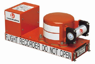
Photo courtesy L-3 Communication Aviation Recorders
A solid-state recorder
Cockpit Voice
Recorders
In almost every commercial aircraft, there are several microphones built into
the cockpit to track the conversations of the flight crew. These microphones
are also designed to track any ambient noise in the cockpit including the noise
of switches and warnings etc. There may be up to four microphones in the
plane's cockpit, each connected to the cockpit voice recorder (CVR), mainly
positioned at:
- Pilot's headset
- Co-pilot's headset
- Headset of a third crew
member (if there is a third crew member)
- Near the
center of the cockpit, where it can pick up audio alerts and other sounds
Any sounds in the cockpit are picked up by these
microphones and sent to the CVR, where the recordings are pre-amplified, digitized
and stored.
Most magnetic-tape CVRs store the
last 30 minutes of sound. As new material is recorded, the oldest material is
overwritten. CVRs that used solid-state storage can record two hours of audio.
CVR recordings can hold important clues to the cause of an accident.
Crash Survivability
Features
The Crash Survivable Memory Unit
(CSMU) is a large cylinder that bolts onto the flat portion of the recorder and
is engineered to withstand extreme heat, violent crashes and pressure. In older
magnetic-tape recorders, the CSMU was inside a rectangular box.
|
Source: L-3 Communication Aviation Recorders
|
Using three layers of materials, the CSMU in a
solid-state black box insulates and protects the stack of memory boards that
store the digitized information. The materials used in the fabrication of a
CSMU are:
- Aluminum housing around the stack of memory cards.
- High-temperature insulation:
Dry-silica material,1 inch (2.54 cm) thick, provides high-temperature
thermal protection during post-accident fires.
- Stainless-steel/ Titanium shell: About 0.25 inches (0.64 cm)
thick.
To ensure the quality and survivability of black
boxes the CSMUs are thoroughly tested. The tests that make up the
crash-survival sequence are:
- Crash impact: The CSMU is
subjected to an impact of 3,400 Gs using an air cannon.
- Pin drop: To test the unit's penetration
resistance, a 500-pound (227-kg) weight with a 0.25-inch steel pin
protruding from the bottom is dropped onto the CSMU from a height of 10 feet
(3 m).
- Static crush: Apply 5,000 psi of
crush force to each of the unit's six major axis points for 5 minutes.
- Fire test: The unit is placed
into a propane-source fireball at 2,000 deg C for one hour. The FAA
requires that all solid-state recorders be able to survive at least one
hour at this temperature.
- Deep-sea submersion: The CSMU is
placed into a pressurized tank of salt water for 24 hours.
- Salt-water submersion: The CSMU
must survive in a salt water tank for 30 days.
- Fluid immersion: Various CSMU
components are placed into a variety of aviation fluids, including jet
fuel, lubricants and fire-extinguisher chemicals.
Post Crash Procedures
The distinct orange color, along with the strips of reflective tape attached to
the recorders' exteriors; help investigators locate the black boxes following
an accident. In the case of a mishap over water, the cylindrical Underwater
Locator Beacon (ULB) is used to track the Black Box. If a plane crashes into
the water, the beacon sends out pulses at 37.5 kilohertz (kHz) and can transmit
sound as deep as 14,000 feet (4,267 m). Once the beacon begins
"pinging," it pings once per second for 30 days. The beacon is
powered by a battery that has a shelf life of six years.
In the United
States, when investigators locate a black
box it is transported to the National Transportation Safety Board (NTSB).
Special care is taken in transporting these devices in order to avoid any
(further) damage to the recording medium. In cases of water accidents,
recorders are placed in a cooler of water to keep them in the same environment
from which they were retrieved, until it gets to a place where it can be
adequately disassembled.
|
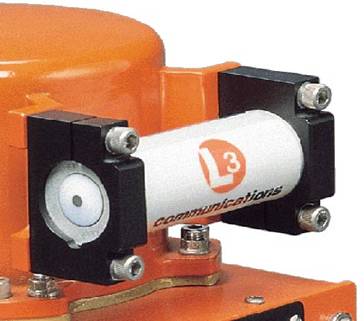
Photo courtesy L-3 Communication Aviation Recorders
A close-up of an underwater locator
beacon
|
Information Retrieval
After finding the black boxes, investigators
download the data from the recorders and attempt to recreate the events of the
accident. Black-box manufacturers supply the NTSB with the readout systems and
software needed to do a full analysis of the recorders' stored data.
If the FDR is not damaged, investigators can
simply play it back on the recorder by connecting it to a readout system. Very
often, recorders retrieved from wreckage are dented or burned. In these cases,
the memory boards are removed, cleaned up and a new memory interface cable is
installed. Then the memory board is connected to a working recorder.
A team of experts is usually brought in to
interpret the recordings stored on a CVR. This group typically includes a
representative from the airline, a representative from the airplane
manufacturer, an NTSB transportation-safety specialist and an NTSB air-safety
investigator. This board attempts to interpret 30 minutes of words and sounds
recorded by the CVR.
|
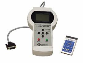
Photo courtesy L-3 Communication Aviation Recorders
This portable interface can allow
investigators quick access to the data on a black box.
|
Both the FDR and CVR are invaluable tools for any
aircraft investigation and provide important clues to the cause that would be
impossible to obtain any other way. As technology evolves, black boxes will
continue to play a tremendous role in accident investigations.
Aircraft
Reconstruction as an Investigation Technique
Generally, air crashes are investigated by the
FAA, FBI and the NTSB teams using the information available from the FDRs and the
CVRs recovered from the crash site. However, in some cases when the cause of
the accident still remains uncertain (eg. The De Havilland Comet crash in 1954)
and/or it is important to establish and confirm the exact cause of the crash in
order to rule out several controversial causes (eg. The TWA 800 crash in1996)
it has been decided to put together entire parts of the aircraft from the bits
salvages by the rescue teams. The procedure is expensive and demanding but the
results produced have been of immense help to the teams for further
investigations.
The
accidents:
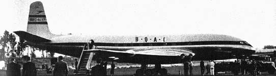
De
Havilland Comet (1954): The de Havilland Comet was the first commercial jet
aircraft with a pressurized cabin and marked the beginning of long distance air
travel, as we see it today. On January
10, 1954, a Comet registered G-ALYP and operated by the British
Overseas Airways Corporation took off from Rome
on a regular flight to London.
After an uneventful take-off, the aircraft abruptly lost contact with the
ground tower as it passed FL260 in it climb to its cruising altitude of FL360.
Moments later the jet literally rained down over the Mediterranean
Sea in hundreds of pieces. The CVRs and FDRs provided little clues
as to why the jet simply exploded without any kind of warning, killing 6 crew
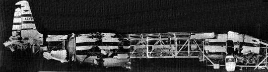
members and 29 passengers. The Royal Aircraft Establishment then decided to
reconstruct the entire fuselage from the bits and pieces that were salvaged.
This technique helped in establishing the cause of the explosion – fatigue
failure of the thin aluminum skin because of stress concentration at the edges
of the square cut-outs for the windows. The jet had undergone an explosive
decompression of its pressurized cabin which had hurled its components outward.
The reconstruction was indeed a revealing study and established the origin
point of the fatal crack.
Reconstruction
pictures:
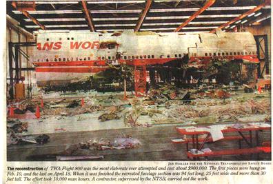
The TWA
Flight 800 (1996): This Boeing 747-131, registered N93119, was also on a
routine flight from New York to Paris when it exploded at FL137, 12 minutes
after take-off, killing all 230 lives on board and “spraying” its parts 10
miles off the Atlantic shore. For this crash, a host of theories, including a
bomb detonation and a missile attack, cropped up and were hyped to such an
extent that the safety standards of the airline industry were brought into
question. A 3D reconstruction of the complete aircraft was planned in order to
firmly rule out all the wrong theories explaining the crash. While salvaging
the parts the exact position where each part was found in the sea was recorded.
Every part of the aircraft is embossed with a number which indicates its
distance from the nose in feet. This provides an idea of where exactly the part
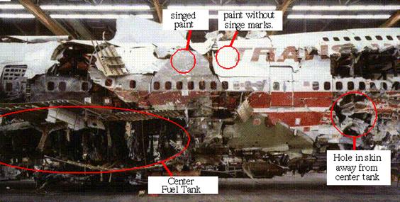
came from. The complete reconstruction involved 876 pieces. The process
indicated that the front part of the aircraft had exploded and had led to the
disaster. An explosion in the center fuel tank is suspected to be the main
reason for the crash. Similarities with previous crashes of the Pan Am 103, UAL
811 and the Air India 182 crashes also indicated the front cargo door design as
a possible culprit.
Some
pictures of the reconstruction:

Some
Statistics
By
Aircraft Model
|
Model
|
Events
|
No. Flights
|
|
|
|
|
|
Aerospatiale Concorde
|
1
|
0.08 Million
|
|
Airbus A300
|
8
|
8.0 Million
|
|
Airbus A310
|
5
|
2.7 Million
|
|
Airbus A319/320/321
|
4
|
6.0 Million
|
|
Boeing 727
|
46
|
70.0 Million
|
|
Boeing 737
|
46
|
76.0 Million
|
|
Boeing 747
|
23
|
14.8 Million
|
|
Boeing 757
|
4
|
7.2 Million
|
|
Boeing 767
|
3
|
6.5 Million
|
|
British Aerospace BAe 146
|
4
|
4.5 Million
|
|
Embraer 110 Bandeirante
|
28
|
7.5 Million
|
|
Embraer 120 Brasilia
|
5
|
7.0 Million
|
|
Fokker F-28
|
20
|
8.5 Million
|
|
Fokker F-70/F-100
|
3
|
4.5 Million
|
|
Lockheed L-1011 Tristar
|
5
|
5.5 Million
|
|
McDonnell Douglas DC-9
|
42
|
55.5 Million
|
|
McDonnell Douglas DC-10
|
15
|
7.6 Million
|
|
McDonnell Douglas MD-80
|
8
|
20 Million
|
|
McDonnell Douglas MD-11
|
4
|
0.7 Million
|
|
Saab 340
|
3
|
9.0 Million
|
|
|
Accident Rates By Year:
The following table provides statistical information regarding the safety
of each year since 1970. Hijackings are excluded. * 'Rate 1' is defined as
"the average number of fatal accidents per million departures."
* 'Rate 2' is defined as "the average number of fatalities per
million departures."
|
|
|
|
Year
|
No. Accidents
|
No. Fatalities
|
Rate 1 *
|
Rate 2 *
|
No.Departures
|
|
|
|
|
|
|
|
|
1970
|
69
|
1583
|
11.5
|
263.8
|
6.0 Million
|
|
1971
|
50
|
1453
|
8.06
|
234.4
|
6.2 Million
|
|
1972
|
73
|
2556
|
10.7
|
375.9
|
6.8 Million
|
|
1973
|
68
|
2135
|
9.6
|
300.7
|
7.1 Million
|
|
1974
|
57
|
2082
|
7.9
|
289.1
|
7.2 Million
|
|
1975
|
49
|
1174
|
6.5
|
156.5
|
7.5 Million
|
|
1976
|
57
|
1807
|
6.95
|
220.3
|
8.2 Million
|
|
1977
|
55
|
1736
|
6.2
|
195.1
|
8.9 Million
|
|
1978
|
61
|
1288
|
6.8
|
143.1
|
9.0 Million
|
|
1979
|
69
|
1855
|
7.1
|
191.2
|
9.7 Million
|
|
1980
|
43
|
1358
|
4.4
|
140.0
|
9.7 Million
|
|
1981
|
40
|
920
|
4.1
|
93.8
|
9.8 Million
|
|
1982
|
35
|
1164
|
3.5
|
117.6
|
9.9 Million
|
|
1983
|
35
|
1355
|
3.5
|
136.9
|
9.9 Million
|
|
1984
|
34
|
624
|
3.3
|
60.0
|
10.4 Million
|
|
1985
|
40
|
2367
|
3.8
|
223.3
|
10.6 Million
|
|
1986
|
41
|
926
|
3.5
|
79.8
|
11.6 Million
|
|
1987
|
42
|
1351
|
3.6
|
115.4
|
11.7 Million
|
|
1988
|
63
|
1734
|
5.2
|
143.3
|
12.1 Million
|
|
1989
|
61
|
1855
|
4.95
|
150.8
|
12.3 Million
|
|
1990
|
39
|
781
|
3.1
|
61.9
|
12.6 Million
|
|
1991
|
54
|
1161
|
4.0
|
86.0
|
13.5 Million
|
|
1992
|
57
|
1552
|
4.1
|
112.4
|
13.8 Million
|
|
1993
|
53
|
1275
|
3.8
|
90.4
|
14.1 Million
|
|
1994
|
54
|
1493
|
3.6
|
100.2
|
14.9 Million
|
|
1995
|
51
|
1167
|
3.4
|
77.2
|
15.1 Million
|
|
1996
|
52
|
1945
|
3.25
|
121.5
|
16.0 Million
|
|
1997
|
40
|
1235
|
2.45
|
75.7
|
16.3 Million
|
|
1998
|
40
|
1325
|
2.42
|
80.3
|
16.5 Million
|
|
1999
|
43
|
674
|
2.29
|
36.0
|
18.7 Million
|
|
2000
|
32
|
1231
|
1.52
|
58.34
|
21.1 Million
|
|
2001
|
TBA
|
TBA
|
TBA
|
TBA
|
TBA
|
|
References:
1) www.howstuffworks.com
2) www.air-disaster.com
3) www.bath.ac.uk/~en8gkh/geomenu.htm
4) Air&Space
magazine: Sept 1997