Passive Thermal Control System
Passive thermal control systems involve no mechanical moving parts or fluids. There is no power consumption which ensures its low mass and cost. It is highly reliable due to its design simplicity, implementation and testing. The only drawback of PTCS is its low heat transport capability except for heat pipes when compared with ATCS.[1]
PTCS includes the following components:
Contents
Thermal Insulations
Introduction [2]
Thermal insulations comprise of low thermal conductivity materials which are combined in a manner such that the system has an even lower thermal conductivity. Conventionally, in fiber-type, powder-type and flake-type insulations, throughout an air space, the solid material is finely dispersed. To characterize such systems, an effective thermal conductivity is used, which depends on both the thermal conductivity and surface radiative properties of the solid material, and also the characteristics and volumetric fraction of the void or air space. Bulk density (solid mass/total volume) is a special parameter of the system, which is very highly dependent on the manner of packing of the materials. If small hollow spaces or voids are formed as a result of bonding or fusing portions of the solid material, a rigid matrix will be created. A system is referred to as cellular insulations if such spaces are sealed from each other. Foamed systems, those made from plastic and glass materials in particular, are an example of such rigid insulations. Reflective insulations comprise of parallel, multilayered, thin sheets or foils which have a high reflectivity. These sheets or foils are spaced to reflect radiant energy back to its source. The foil spacing is designed to restrict air motion, and it is evacuated in high-performance insulations. The air in the void space reduces the effective thermal conductivity of the system in all kinds of insulations. Please note that heat transfer through any insulation system may consist of several modes: conduction through the solid materials; conduction or convection through the air in the void spaces; and radiation between the surfaces of the solid matrix. Effective thermal conductivity accounts for all of these processes.
Multi Layer Insulation (MLI)[3]
Multilayer Insulation (MLI) is used to minimize temperature gradients throughout the satellite and to control heat transfer rates. MLI blankets work in both ways: they prevent both excessive heat loss from a satellite component and also prevent excessive heating from the external environmental fluxes, and other sources. Most satellites today are covered with MLI blankets. Cutouts are provided at places for radiators to reject internally generated waste heat. If lesser thermal insulation is required, single layer radiation barriers may be used, in place of MLI, since they are cheap to manufacture and also lighter.
In practice, just by increasing the number of layers beyond a certain value, performance cannot be improved. As the number of layers increases, radiative heat transfer becomes small compared to conductive “shorts” between layers and other losses. About 25 layers are usually sufficient to obtain a minimum overall conductance value.
Working of MLI

Lets understand this with an example.
Imagine a 1 surface in outer space, at 400 K. Assume that its emissivity is 1. Also assume that it is facing away from the sun (i.e. in the direction opposite to the sun) or other heat sources. Using the Stefan–Boltzmann law, we can show that this surface will radiate 1452 watts. Now if we place a thin (but opaque) layer 1 cm away from the plate (thermally insulated from it), and also with an emissivity of 1, then this layer will cool until it is radiating 726 watts from both its sides. Once this point is reached, everything will be in balance. The new layer gets 1452 watts from the plate, out of which 726 watts is radiated back, and 726 watts is radiated to space. The original plate still radiates 1452 watts, but gets 726 back from the new layer, which makes the net loss to be 726 watts. So overall, the radiation losses have been halved by adding the new layer. [4]
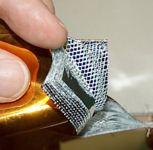
MLI is composed of multiple layers of low-emittance films.
The MLI construction, in its simplest form, is a layered blanket which is assembled from thin embossed Mylar sheets. Each sheet has, on one side, a vacuum-deposited aluminum finish. Because of the embossing, the sheets come in contact at only a few points, thereby minimizing the conductive heat paths between layers. The layers have an aluminum finish on one side only so that the Mylar can act as a somewhat low-conductivity spacer. A construction which gives higher performance is composed of Mylar film metalized (with aluminum or gold) on both sides. These have silk or Dacron net as the low-conductance spacers. [3]
Heat transfer through MLI is a combination of solid conduction, radiation and, under atmospheric conditions, gaseous conduction. All of these forms are minimized in different ways. Interposing as many enclosing reflective surfaces (metallized sheets) as is practically possible between the object being insulated and its surroundings minimizes radiative heat transfer. One can minimize solid conduction heat transfer by minimizing the density of the low-conductance spacers between the reflective surfaces and making the blanket "fluffy" in order to minimize contact between layers. [3]
The heat transfer mechanisms operate simultaneously and interact with each other. Therefore, a useful technique is to derive either an apparent thermal conductivity, , or an effective emittance, , through the blanket. We can experimentally derive both the values for steady state heat transfer.
Theoretically, for a highly evacuated MLI system, the emittance for a blanket comprising of N non-contacting layers having emissivities and on opposite sides is computed as: [3]
In satellite applications, the MLI is full of air at launch time. As the rocket ascends through the atmosphere, this air should be able to escape without damaging the blanket. Therefore, holes or perforations are required in the layers, even though this has an associated reduction in effectiveness.
MLI blankets are traditionally constructed with sewing technology. The layers are cut, then stacked on top of each other, and finally sewn together at the edges. Seams and gaps in the insulation are the cause of most of the heat leakages through MLI blankets. A new method is being developed to use polyetheretherketone (PEEK) tag pins (similar to plastic hooks used to attach price tags to garments) to fix the film layers in place instead of sewing to improve the thermal performance.[5]
In some applications the insulating layers must be grounded, so that they do not build up a charge and arc, which cause radio interference. Satellites may also use MLI as a first protection against dust impacts.
Surface Coatings and Paints
A satellite or a space station can have a variety of surface finishes because of the difference in thermal requirements from region to region. Thermal coatings and paints must be compatible with the environment. They must also be resistant to both radiation and atomic oxygen that they will be constantly exposed to.
Different types of finishes are used to provide various degrees of thermal control for on-board equipment. Using coatings and paints with different emissivity and absorptivity with different characteristics allows the region or component to either be “warmed” or “cooled” as required. An example of this are radiators that use high emissivity and low absorptivity coatings to help radiate excess heat to space.
Phase Change Materials
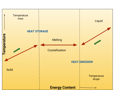
This proposed technology is expected to enable efficient thermal control by maintaining a constant temperature heat sink or source for a wide range of electronic components in rapidly changing thermal environments. The Phase Change Material panel is being designed as a lightweight and flexible component. Even then, it will have high thermal capacity. Thus, it will require less mass and volume than presently used carbon-fiber and aluminum honeycomb composite panels. [6]
Example:[7]
Roccor LLC of Longmont, Colo., is making use of phase change material in a device that is designed to manage internal heat in low-orbit satellites. A product containing paraffin wax within a flat structure is used. When the spacecraft is hot, the paraffin wax acts as a heat sink and turns into a liquid — basically a store of energy. Later on, the heat is released into the satellite to keep temperatures stable.
PCM is one of the developing areas in efficient passive thermal control systems which acts as both a heat sink or a heat source based on the demand of the system.

If you are done reading this page, you can go back to Mechanical Subsystem
References
- ↑ https://en.wikipedia.org/wiki/Spacecraft_thermal_control
- ↑ https://books.google.co.in/books?isbn=0470501960
- ↑ 3.0 3.1 3.2 3.3 Spacecraft Thermal Control Handbook Volume I: Fundamental Technologies, David G. Gilmore
- ↑ https://www.revolvy.com/main/index.php?s=Multi-layer+insulation&uid=1575
- ↑ https://en.wikipedia.org/wiki/Multi-layer_insulation
- ↑ https://techport.nasa.gov/view/89663
- ↑ http://www.puretemp.com/pcmatters/pcm-briefing-110