Reaction Wheels
Contents
Internal Momentum Exchange devices
Unlike aircrafts, spacecrafts can't rely on aerodynamic forces to provide stability.So they have to rely on reaction type devices as actuators for their attitude control in space. These actuators utilise the concept of exchange of momentum. The exchange of momentum happens either between satellite and earth (in case of Magnetorquers), spacecraft and ejected mass from craft (in case of reaction thrusters) or within satellite body.
The devices in which momentum redistribution takes place within the satellite body falls under the category of internal momentum exchange devices. The advantage of these devices is that they do not need any fuel as thrusters do. They require electric motors which can be powered by batteries and the battery can be charged by solar panels. So this proves to be an attractive alternative option.
Types:
- Reaction Wheels
- Momentum Wheels
- Control Moment Gyroscopes (CMGs)
Reaction Wheels
A reaction wheel is a device consisting of a spinning wheel attached to an electric motor (brushless DC), whose speed can be controlled by onboard computer, producing the required torque for attitude control.
It works on the principle of angular momentum conservation of flywheel or disc and satellite body. Each wheel can produce torque only along its axis of rotation. So by mounting three reaction wheels along mutually perpendicular axes, we can get the desired magnitude and direction of torque. However there is a limit to the torque they can produce because the wheels can’t be accelerated and decelerated limitlessly.
Mechanisms for Control/Working
Since reaction wheels are internal momentum exchange devices they can’t alter the total angular momentum of the satellite. But the angular momentum of the satellite can be redistributed between the wheels and satellite body. Therefore the required amount of angular momentum can be transferred to satellite body in order to achieve the desired attitude rates.
Dynamics of the satellite using reaction wheels
In space there are disturbances (like aerodynamic torque(in LEO), gravity gradient torque, solar radiation pressure torque) that provide external torques(Ne) to the satellite which tend to destabilize the satellite. Therefore it is necessary to understand the dynamics of the satellite and model the same to actively control the attitude of satellite.
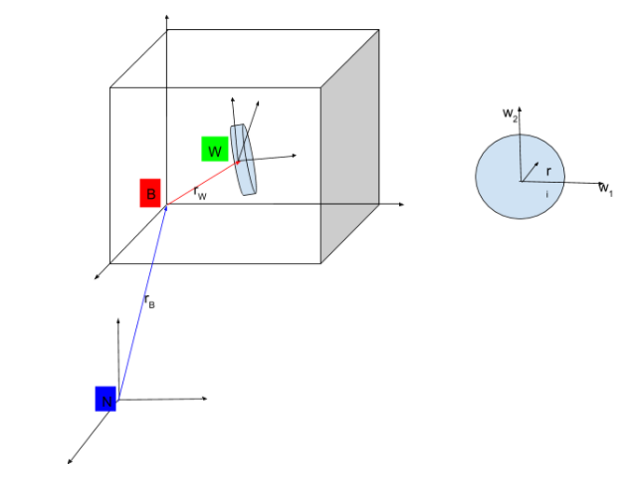
The total angular momentum of the system (satellite body + reaction wheels) about center of mass of the system can be written as [1]
While dealing with satellite dynamics we need a rotating reference frame. The rate of change of a vector in two frames can be related by the equation: [2]
Where I and B are two frames and ![]() is the angular velocity of B frame with respect of N frame.
is the angular velocity of B frame with respect of N frame.
Now we have another relation relating torque applied to the system and the change in angular momentum of the system: [3]
Where subscript p is any arbitrary point in space and c is for center of mass. ![]() is the total external moment applied on the system.
is the total external moment applied on the system.
Now since we wrote our total angular momentum of the system about the center of mass, the second term in the above equation can be dropped.
Hence we are left with ![]() .
.
By now, you must have observed that ![]() is nothing but the inertial derivative of
is nothing but the inertial derivative of ![]() . Again, we have the relation [3]
. Again, we have the relation [3] ![]() , where:
G is the center of mass of the body,
, where:
G is the center of mass of the body,
[I] is the inertia matrix in frame fixed to G
![]() is the angular rate of body.
is the angular rate of body.
Note that the challenge is to find ![]() and
and ![]() about the center of mass of the system, rather than their own centers of mass, which can be easily done. Please refer to this.
about the center of mass of the system, rather than their own centers of mass, which can be easily done. Please refer to this.
Now we have everything, but before moving ahead let’s state some assumptions made to during the final derivation. It’s assumed that the center of mass of satellite body and center of mass of the system are very close. Also the wheel of reaction wheel is assumed to be uniform.
Let's substitute equation 1 in equation 2.
After several manipulations, we get,
Note: ![]() and
and ![]() in the above expression are the derivatives in the B frame and the W frame respectively.
in the above expression are the derivatives in the B frame and the W frame respectively. ![]() is the unit vector along the axis of rotation of the wheel and
is the unit vector along the axis of rotation of the wheel and ![]() is the inertia about the axis of rotation of the wheel.
is the inertia about the axis of rotation of the wheel.
In the above equation it is visible that we are able to relate the angular speed of the wheel and the disturbance torque acting on the satellite. And what we have control is on the speed of the reaction wheel. Therefore it can be accelerated and decelerated suitably to actuate the satellite.
Limitations of Reaction Wheels
- Has moving parts
- Can’t produce external torque.
- Size and mass constraints
- Limited by max rotation rate
- Accumulation of momentum (momentum saturation).
- It can’t be independently used (it needs momentum unloading, which is typically achieved by magentorquers)
- Shouldn’t be operated near 0 rpm (due to dominating friction).
If you are done reading this page, you can go back to Attitude Determination and Control Subsystem
