SNAP (Remove Before Flight)
Contents
What is Snap?
Snap is the event of ejection of the satellite from the launch vehicle.There is a type of circuit known as RBF circuit which ensures that satellite starts operation only after the ejection from the launch vehicle.The RBF circuit will be used to detect the jettisoning of the space craft from the launch vehicle. However, RBF is the standard word used for this but we’ll use Snap in this doc.
Generally the small satellite missions have two kinds of switching mechanism available:
- Remove before flight pin integrated in their (Electrical Power System) EPS card which disconnect the solar powered battery with the entire circuit. These pins are used to control/test and maintain the functionality of the satellite on ground and are removed before being integrated in the launch vehicle.
- End switches, these switches activates the satellite when it is deployed in the orbit by a LV.
Two snap switches should be incorporated in a satellite. These switches could be either electromechanical switches mounted diagonally opposite on as appropriate panel of the satellite or solid-state switches housed inside the satellite. The two snap switches are configured electrically in series such that the satellite is powered “ON” only when both switches are activated after the separation of satellite from launch vehicle
Why do we need Snap?
We need Snap circuit in order to ensure that our satellite should not consume power before the ejection from the launch vehicle so that if in any case if the launch is delayed then also our satellite will have enough power left. After the Snap switch is detected by the power circuit, it switches on the other circuits in a predefined sequence. Another reason is that if the satellite gets powered ON before ejection, there is a possibility that premature deployments would take place, damaging all the satellites on-board the launch vehicle, and in the worst case, destroying the launch vehicle itself.
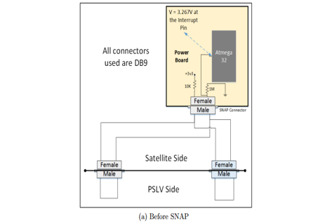
Example Snap Circuit - Pratham
Before Ejection
Before the ejection two connectors from satellite side are connected to the launch vehicle side.This establishes a connection between the Vcc and GND.Since the ratio of the resistor used(see in figure 1) is 1:100 so the voltage level at the interrupt pin is approx. equal to Vcc (approx. 0.99Vcc).
After Ejection
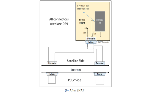
After ejection occurs interrupt pin is pulled down to 0. LOW at the INT pin for some amount of time causes atmega to wake up from sleep and starts working. A level-triggered interrupt is an interrupt signaled by maintaining the interrupt line at a high or low logic level. It is used so that microcontroller should not wake up due to noises.Two connectors are used for redundancy so that unless both the connectors are disconnected the INT pin should not go LOW.
Testing SNAP
In SNAP circuit most crucial components are the connectors which are connected to the launch vehicle. So they are tested rigorously to ensure that they should not open due to disturbance. They should pass vibration testing so that due to shaking or vibration the connectors should not open. In order to test Snap, the connectors are first kept connected, then we disconnect them and observe that the microcontroller doesn't wake up for 50 minutes. This time limit i.e. 50 minutes comes from the fact that the satellite should not affect the launch vehicle communication till the ejection of other satellites onboard. This time may change based on the requirements of the space agency launching your satellite.
If you are done reading this page, you can go back to Electrical Subsystem

