Rotational
Motion of a Torque-Free Rigid Body
The animations on this page show the natural rotational motion of a
free rigid body about its center of mass. The rotational motion of the
body is depicted by showing the changing attitude of its kinetic energy
ellipsoid. The principal geometrical axes of the ellipsoid (shown by
white segments in all the animations) lie along the principal axes of
inertia of the body, with the longest geometrical axis along the minor
principal axis of inertia and the shortest along the major principal
axis of inertia. The white segments in the animations thus show the
instantaneous orientation of the principal axes frame of the body. The
black lines depict the (nonrotating) inertial reference frame for
comparison.
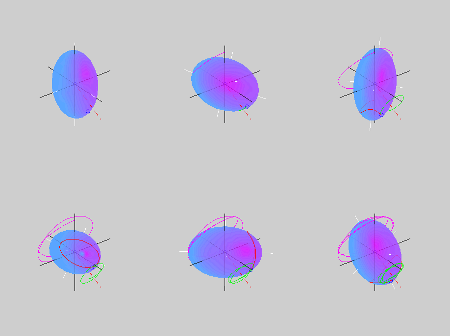
 The animation on the right shows the rotational motion
that results when the initial angular velocity of the body is close to
its minor principal axis of inertia (also the longest axis of the
ellipsoid). The blue circle shows the tip of the angular velocity
vector. As the motion evolves, an inertial observer sees the angular
velocity vector tracing out the herpolhode
shown in green. However, an observer rotating with the body sees
the same angular velocity vector tracing out the polhode shown in red. The polhode
is closed, indicating that the body frame components of the angular
velocity vector vary in a periodic fashion. The red dashed line shows
the direction of the constant angular momentum vector. The pink curve
shows the path traced out by a point on the minor principal axis of
inertia.
The red polhode in the animation on the right appears to be rolling on
the green herpolhode. This is not a mere coincidence. The seemingly
complicated rotational motion of a free rigid body has a remarkably
simple description that was first discovered by Poinsot: the rotational motion is such that the
kinetic energy ellipsoid rolls without slipping on a fixed
two-dimensional plane. The fixed plane, known as the invariant
plane, is a stationary plane that is perpendicular to the angular
momentum vector and tangent to the kinetic energy ellipsoid. The
location and orientation of the invariant
 plane are determined by the initial angular velocity and
the initial
orientation of the kinetic energy ellipsoid. The tip of the angular
velocity vector is also the point of contact between the ellipsoid and
the invariant plane. As the ellipsoid rolls without slipping, the point
of contact traces out the herpolhode on the invariant plane and the
polhode on the ellipsoid.
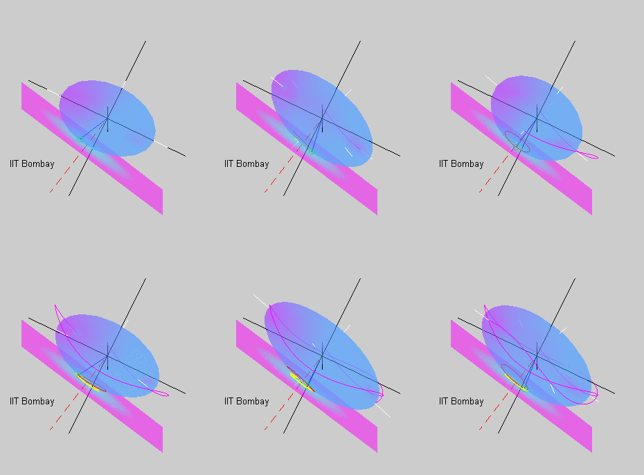
The animation on the left shows the kinetic energy ellipsoid rolling on
the
invariant plane in the case where the initial angular velocity is close
to the major principal axis of inertia or the shortest geometrical axis
of the ellipsoid. In this case the ellipsoid rolls on its flatter side
tracing out the yellow herpolhode and the red polhode.
The motion of the minor principal axis depicted by the pink curve
consists of precession in
which
the axis goes around, and nutation
in which the axis bobs up and down.
In both the animations above, the polhode is a closed curve either
encircling the minor or the major axis, indicating that the angular
velocity vector remains ''close'' to its initial value. This is because
the states of spin about the minor and major axes are stable states for
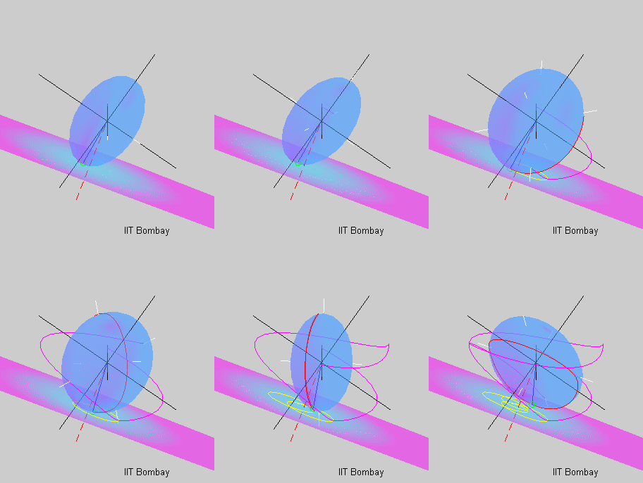
a rigid body.  The last animation
on this page shows the rotational motion that follows an initial
state of near spin about the intermediate principal axis of inertia.
The red polhode almost connects the opposite ends of the intermediate
axis, showing that the body transitions between spinning about the
positive and negative intermediate axis. Even the pink curve showing
the motion of the minor axis as well as the yellow herpolhode appear
more erratic. This is because the state of spin about the intermediate
axis is unstable, and even a small initial perturbation leads to a
large departure.
The animations on this page depict the motion of an asymmetric rigid
body whose principal moments of inertia are all unequal. The motion of
an axisymmetric body having two of its
principal moments of inertia equal is simpler to visualize.
The animations
appearing on this page were created with the help of Debashish Bagg.
 The animation on the right shows the rotational motion
that results when the initial angular velocity of the body is close to
its minor principal axis of inertia (also the longest axis of the
ellipsoid). The blue circle shows the tip of the angular velocity
vector. As the motion evolves, an inertial observer sees the angular
velocity vector tracing out the herpolhode
shown in green. However, an observer rotating with the body sees
the same angular velocity vector tracing out the polhode shown in red. The polhode
is closed, indicating that the body frame components of the angular
velocity vector vary in a periodic fashion. The red dashed line shows
the direction of the constant angular momentum vector. The pink curve
shows the path traced out by a point on the minor principal axis of
inertia.
  plane are determined by the initial angular velocity and
the initial
orientation of the kinetic energy ellipsoid. The tip of the angular
velocity vector is also the point of contact between the ellipsoid and
the invariant plane. As the ellipsoid rolls without slipping, the point
of contact traces out the herpolhode on the invariant plane and the
polhode on the ellipsoid.
 The last animation
on this page shows the rotational motion that follows an initial
state of near spin about the intermediate principal axis of inertia.
The red polhode almost connects the opposite ends of the intermediate
axis, showing that the body transitions between spinning about the
positive and negative intermediate axis. Even the pink curve showing
the motion of the minor axis as well as the yellow herpolhode appear
more erratic. This is because the state of spin about the intermediate
axis is unstable, and even a small initial perturbation leads to a
large departure.