Transportation
Several mechanical and electrical aspects determine the transportation requirements needed for satellite.
Contents
Mechanical Factors
- Vibration and Shock Handling: Vibration and shock impacts on satellite while travelling are as follows:
- Some satellite components are vulnerable to shock and random vibration.
- Vibration may lead to some deformities in satellites.
- Thermal Control: Due to transportation of satellite, a range of temperature changes occurs in satellite. As we pass through different places, temperature changes from place to place. To counter this problem proper thermal control is required to protect components
- Pressure Management: During air transportation , transportation box is placed in the cargo compartment of the aircraft. The cargo compartment of the aircraft undergoes pressure fluctuations. To ensure pressure management we need a pressure equalisation system.
- Contamination protection: Some of the critical components of satellite needs to be protected from humidity to prevent corrosion and contamination.
Electrical Factors
- Electrostatic Discharge (ESD):[1] Electrostatic discharge (ESD) is the sudden flow of electricity between two electrically charged objects caused by contact, an electrical short, or dielectric breakdown. A buildup of static electricity can be caused by tribocharging or by electrostatic induction. The ESD occurs when differently-charged objects are brought close together or when the dielectric between them breaks down, often creating a visible spark.
- RF Radiation
Vibration and Shock Handling
Passive Vibration Isolation (PVI) System
A PVI System makes use of materials and mechanical linkages that absorb and damp the mechanical waves. A general vibration isolation system consist of some basic components:
- Mass
- Spring
- Damper
Dampers help in dissipation of vibration energy into heat energy. A PVI system can be simplified with the system shown in the figure below:

Transmissibility Curve [2]
It gives an indication of how much source vibration will be transmitted through the interface to the satellite. It is a relative measure given as a ratio of vibration at two points: one on the top of the isolator and one on the source. Here is an example of a transmissibility curve of negative stiffness isolation system with natural frequency 0.5Hz.
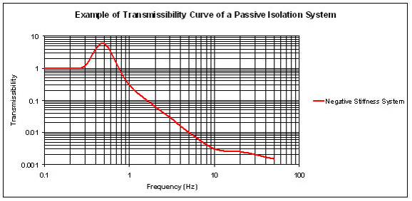
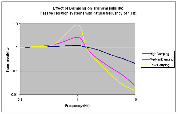
The transmissibility hovers around initially as the frequency of source reaches natural frequency, the amplitude rises catastrophically. We need dampers to damp this kind of vibration to ensures the structural stability and integrity of any payload.
Types of PVI Systems
- Pneumatic or air isolators
- Mechanical springs and spring-dampers
- Pads or sheets of flexible materials such as elastomers, rubber, cork, dense foam and laminate materials.
- Negative-stiffness isolators
- Wire rope isolators
Active Vibration Isolation (AVI) System [2]
It can be modeled as spring along with a feedback circuit which consists of a sensor , a controller, and an actuator. The acceleration (vibration) signal is processed by a control circuit and amplifier. Then it feeds the electromagnetic actuator, which amplifies the signal. As a result of such a feedback system, a considerably stronger suppression of vibrations is achieved compared to ordinary damping.
Sensors for Active Isolation
- Piezoelectric Accelerometer:
- Produces current on mechanical stress
- Magnitude of current depends on the value of acceleration
- Value of current make the actuators produce cancelling vibration
- Geophones
- A geophone is a device that converts ground movement (velocity) into voltage
- According to this voltage the actuators are initiated for producing cancelling signal
- Proximity sensors
- Sends EM waves and detects the change in return signal(field)
- According to variation in return signal, actuators are actuated for producing cancelling signal
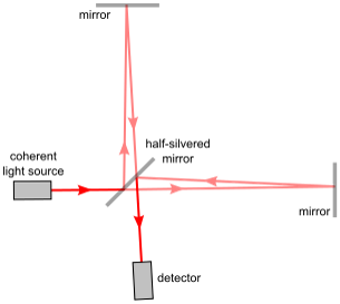
- Interferometers:
- In an interferometer, light from a single source is split into two beams that travel different optical paths, then combined again to produce interference. The resulting interference fringes give information about the difference in optical path length.
- The phase difference in interference pattern helps in cancelling the vibration.
Actuators for Active Isolation
- Linear motors: A linear motor is an electric motor that has had its stator and rotor "unrolled" so that instead of producing a torque (rotation) it produces a linear force along its length.
- Pneumatic actuators: A pneumatic control valve actuator converts energy (typically in the form of compressed air) into mechanical motion. The motion can be rotary or linear, depending on the type of actuator.
- Principle: A Pneumatic actuator mainly consists of a piston or a diaphragm which develops the motive power. It keeps the air in the upper portion of the cylinder, allowing air pressure to force the diaphragm or piston to move the valve stem or rotate the valve control element.
- Piezoelectric motors: A piezoelectric motor or piezo motor is a type of electric motor based on the change in shape of a piezoelectric material when an electric field is applied. Piezoelectric motors use the converse piezoelectric effect of piezoelectric sensors, in which deformation or vibration of the piezoelectric material produces an electric charge. An electrical circuit makes acoustic or ultrasonic vibrations in the piezoelectric material, which produce linear or rotary motion
Active vs Passive Vibration Isolation
| FEATURE | PASSIVE | ACTIVE |
|---|---|---|
| Isolation Range | > 5 HZ | > 0.7 Hz |
| Low frequency resonance | 2-5 Hz | None |
| Amplification at resonance | 4-9 times | N/A |
| High Center of Gravity (Decreases Efficiency ) | Yes | No |
| Isolation in All Six Degrees of Freedom | No | Yes |
| Air Supply Requirements | Air Supply (pneumatic isolator) | None |
| AC power | None | 110-220 V AC supply |
| Price | Low to Moderate | High to Moderate (around 5000$) |
Thermal Control
Thermal coupling between ambient and satellite happens through:
- Natural convection between satellite and inner wall of Satellite Transportation System (STS)
- Conduction through the walls of STS
- Natural convection through the outer walls of STS to the ambient during storage and forced convection during movement.
Passive Thermal Control (PTC) System
Passive thermal control system (PTCS) is used to keep all the spacecraft's component systems within acceptable temperature ranges during all mission phases without the use of any power or active part or material.
Some components of a PTC System are:
Thermal Fillers
To improve the thermal coating at select interfaces. Fillers are used to increase heat transfer between contacting surfaces.
Thermal Doublers
To spread on the radiator surface the heat dissipated by equipment, thereby increasing surface area
Thermal Washers
To reduce the thermal coupling at select interfaces
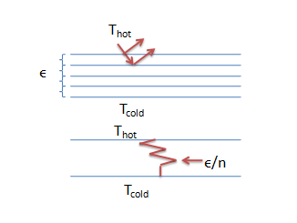
Multi-layer Insulation (MLI)
Protects the spacecraft from excessive solar rays. Acts as a radiation barrier.
Coatings
To change the thermo-optical properties of external surfaces
Radiators
To cool the components by radiating heat to outer space.
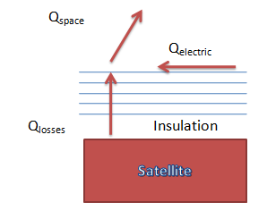
Principle: direct coupling with deep space
q(space)= q(loses) + q(electric)
Active Thermal Control (ATC) system
It does the same work as PTCS but uses power or active part for temperature regulation. Some components of an ATC system are:
Temperature Sensors
- Thermistors – Semiconductors whose resistance varies with temperature
- Resistance thermometers – Pure platinum conductor whose resistance changes with temperature
Heaters
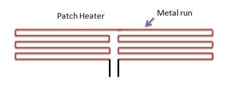
- Additional source of heat inside to control temperature .
- Controlled by thermostats (local or central)
- Flat sheet heaters use the Joule effect
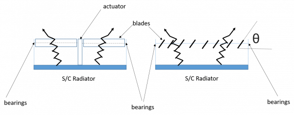
Louvers
- Accommodate extreme variation of energy.
- Shield radiator surfaces to moderate heat flow to space
- Principle: Bi-metallic spring sense the radiator temperature, open/close the radiator to deep space.
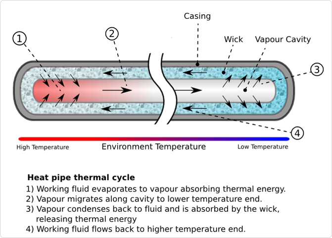
Heat Pipes
- Used to transfer heat from one area to another
- Heat at one end evaporates the working fluid, absorbing heat
- Vaporized working fluid flows to cold end and condenses, releasing heat
- Wicking material returns fluid to hot end
- Provide high heat transfer rates even with small temperature differences
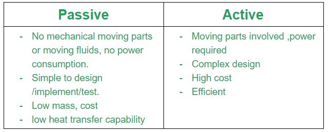
Comparison of Passive and Active Thermal Control
RF and ESD Protection
- The resistance between one end of the STS to other end is kept less than 1 ohm.
- The satellite inside STS is also electrically connected to the STS through a braid , which ensures low resistance between the satellite and the STS.
- Under these circumstances the STS acts like a faraday cage. The double walled panel of the STS is also expected to give good shielding effect for both electric and magnetic field. Thus the satellite is protected from RF .
- The ESD can be classified into two types, namely, the one caused by electric charge accumulated on the operating personnel and the other caused by charging of STS when it encounters with plasma environment.
- Man made ESD does not cause any problem because the container is always grounded and any amount of charge can not reach the satellite .
- Charging due to space plasma does not occur because the STS does not encounter the space plasma.
If you are done reading this page, you can go back to Mechanical Subsystem
